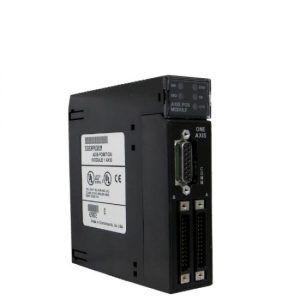
Mô đun Ge Fanuc IC697MDL752 , 90-70 Series Module , 32 output points
Ge Fanuc IC697MDL752 , 90-70 Series Module , 32 Output Points
Product Description
The GE Fanuc 90-70 Series module IC697MDL752 is a 32-point module that delivers 12 Volts and 0.5 Amperes of current. This module provides a high level of inrush current, which makes the IC697MDL752 ideal for a wide array of loads, such as motor starters and solenoids. To find the ON-OFF status of each point of the circuit, locate the LED indicators on the top of the module. In order to ensure correct alignment with similar modules in the field, the module is properly keyed. This IC697MDL752 module is configured using MS-DOS or programming software that rides on either Windows NT or Windows 95. This is usually over the TCP/IP protocol over Ethernet cable or SNP port. The programming configuration is downloaded and installed on the programming device. This is done using a device such as a personal computer, IBM XT, PS/2 or AT.
The IC697MDL752 12 Volt output module is compatible with many devices such as motor starters, solenoids, and indicators. It is divided into 4 groups, each having 8 modules. Due to the module’s heat dissipation, the largest current for each of the 4 groups has a 2-ampere limit.
Each output module can deliver a surge current greater than its life-time current rating. This capability is dependent on the device’s current rating and the duration of time the device is powered ON. The IC697MDL752 output module comes without a fuse. However, if one is needed, a ¾ Amp 250 V fuse is fitted for safety purposes.
The output module comes with a mechanical key that provides a fool proof mechanism. This ensures the module is properly positioned and prevents modules from being unintentionally substituted into a slot for a different module type. Each module comes with a key for this purpose.
During installation or removal of the terminal boards, it’s highly recommended that the power is shut off. Once the power has been shut down, the hinged door can be opened to access the jack screw, which firmly secures the terminal board in place.
The terminal board is designed to accommodate wire sizes from AWG 0.36 mm2 to AWG 2.1mm2. It’s crucial to note that a maximum insulation diameter of .135 inch should not be exceeded when dealing with a 2.1mm2 wire for wiring all points. For proper connection, two wires can be terminated on any terminal provided they are of the same size. The terminal board is crafted to accommodate a maximum of 40 2.1mm2 wires. If they are used, they should be placed at least 8 inches from the end of the termination. This creates sufficient space for the hinged door to close with ease.
After all connections are made to the cable modules, it’s recommended that the cable ties wrap tightly around the wire bundles. When handling larger wire bundles, additional cable ties are recommended. A door label circuit is included with each module to show wiring information. If the label is difficult to insert in the hinged door, you can crease the scored edge before insertion.
After completing filed wiring, ensure the terminal board is fastened to the rack. This is achieved by inserting the board strap into the small slots at the bottom card guide grill on the rack. The strap also identifies the terminal board with its accurate mating slot location. For enough ventilation, leave a 6-inch clearance above and below the grill.
| Rated Voltage: | 12 volts DC |
| Number of Outputs: | 32 Outputs (4 groups of 8) |
| Output Current: | 0.5 Amps per point, 2 Amps per group |
| Current Required: | 0.25 Amps |
| Output Voltage Range: | 10 to 15 volts |
| DC Power: | Yes |
Technical Information
Specifications
|
Rated Voltage: OutputsperModule: |
12 volts DC 32 (four groups of 8 outputs each) |
| Isolation: |
1500 volts – any output to backplane 500 volts between input groups |
| Output VoltageRange: OutputCurrent: |
10 to 15 volts 0.5ampsmaximumperpoint 2ampsmaximumpergroup |
| OutputCharacteristics | |
| Inrush Current: | 10 amps maximum for 20 ms |
| Output VoltageDrop: | 1 volt (2 ohms) maximum |
| ResponseTime-On: | 1 ms typical |
| ResponseTime-Off: | 1 ms typical |
| OutputLeakage: | 1mAmaximum |
| Current Required from 5 V Bus: | .25 amp |
| VME | System designed to support the VME standard C.1 |


