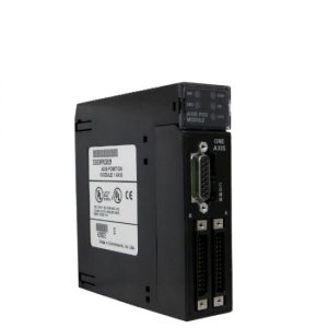
Mô đun GE FANUC IC697MDL340 , 24 Volt AC, 32-Point Input module , Series 90-70
GE FANUC IC697MDL340 , 24 Volt AC, 32-Point Input module , Series 90-70
Product Description
The IC697MDL253 is a 24 Volt AC, 32-Point Input module of the GE Fanuc Series 90-70. This module provides 4 isolated groups of 8 points each. This allows each group of 8 points to be used on a different phase of the AC supply. It comes with a 20ms filter and is compatible with a proximity switch. The input module is resistive and delivers 24 volts AC to the 32 points in the four isolated groups, each with eight points. Characteristics of the input are compatible with a diverse range of proximity switches. At the top of the input module, you will find LED indicators that will display the ON/OFF status of each point on the PLC.
To ensure accurate placement with a similar input module in the field, the module is mechanically keyed. The module does not require jumpers or DIP switches for user configuration. Configuration relies on MS-DOS or Microsoft Windows 95 or Windows NT operating systems and rides on TCP/IP protocol or via the SNP port. The programming software is normally installed on a programming device such as a Personal Computer, AT, IBM or PS/2. IC697MDL253 module is compatible with a myriad of input devices such as electronic proximity switches (both 2 and 3-wire), selector switches, limit switches as well as selector switches. Input current is normally 10mA when ON with a 2-mA leakage current when OFF. There is a preference for 3-wire proximity switches due to their provision of low voltage drop when ON and low current leakage in the OFF state.
This input module is designed to be compatible with 2-wire devices such as two-wire proximity switches which get their power from signal connections. It’s important to note that each type must be examined for compatibility in both ON and OFF states. Each module comes with a mechanical key ring to provide a fool proof functionality that prevents unintentional substitution of one module model for another in a slot. During field wiring, a wire from the source of power to the input power terminal for each group is required. The detachable field terminal board accepts wires sizes ranging from #22 (0.36mm2) to #14(2.10mm2). If they are of the same size, 2 wires can be terminated on one lug.
Wiring procedures:
Firstly, switch off power before removal or installation or installation of terminal boards. You can access the jackscrew that secures the terminal in place by opening the hinged door on the module. The terminal board is then removed by turning the jackscrew counter clockwise until it’s full disengaged. Once this step is complete, swinging it out.
The terminal board accommodates wire ranges from AWG #22 right through AWG#14. A maximum insulation diameter of .135 inches should not be exceeded when using AWG#14. For a perfect connection, two wires can be terminated on any terminal, provided they are of the same size. The terminal board is crafted to accommodate a maximum of 40 AWG #14 (2.10mm2) wires. Wire markers should be placed approximately 8 inches from the terminal end if AWG #14 are to be used. The space provides ample room for closing of the hinged door.
After all connections are completed, secure the wire bundle tightly using cable ties. A door label insert comes with every module to indicate circuit wiring information of the module. There’s a slot provision for insertion of the label on the hinged door. The outside label is color coded for quick identification of voltage type. Blue indicates low voltage while Red indicates high voltage. For ideal ventilation, leave a 6-inch clearance above and below the rack grill.
| Rated Voltage: | 24 volt AC |
| Number of Inputs: | 32 Inputs (4 Isolated groups of 8) |
| Input Current: | 10 mA |
| Current Required: | 0.30 Amps |
| Freq: | 47 to 63 Hz |
| DC Power: | No |
Technical Information
Specifications
|
Rated Voltage: Inputsper Module: |
24 VAC, 47 to 63 Hz Sinusoidal 32 (four groups of eight inputs each) |
| Isolation: |
1500 volts RMS – any input to backplane 500 volts RMS between input groups |
| InputCurrent: | 10mA (typical) at rated voltage |
| InputImpedance: | 2.6Kohms typical |
| InputCharacteristics- | |
| On-stateVoltage: | 13.5 to 30 volts RMS, 47 to 63 Hz Sinusoidal |
| Off-state Voltage: | 0 to 5 volts RMS, 47 to 63 Hz Sinusoidal |
| On-stateCurrent: | 6mAto15mA |
| Off-stateCurrent: | 0 to 2mA (2mA minimum at 5V input) |
| Filter Delay Time: | 20ms typical |
| Current Required from 5VDCbackplanebus: | 0.3 amps |
| VME | System designed to support the VME standard C.1 |


