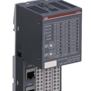
Mô đun GE FANUC IC693APU305 , Input / Output processor module , in the 90 – 30 series of PLCs
GE FANUC IC693APU305 , Input / Output processor module , in the 90 – 30 series of PLCs
Product Description
IC693APU305 is an Input / Output processor module in the 90 – 30 series of PLCs made by GE Fanuc. The module delivers direct processing of rapid signal pulses required for control applications such as velocity measurement, fast response process control, material handling, marking as well as packaging. By direct processing, we imply that the module can sense inputs, process the input information and finally control outputs without having to communicate with a CPU.
For every CPU sweep the I/O processor communicates with the CPU through 32 discrete inputs (%I), 32 discrete outputs (%Q), 15 words of analog inputs (%AI) as well as 6 words of analog outputs (%AQ). The %AQ outputs are used by the CPU program to set up timer values or send other controlling parameters to the I/O Processor. The I/O is configured using a series 90-30 hand-held programmer, a logic master 90-30 or a VersaPro software. Usually, each configuration parameter is set to default which makes it suitable for many applications. Jumpers and DIP switches are not present on the module. Be sure to locate 6 green LEDs at the top of the module. These indicators display the module’s operating status, status of hardware outputs as well as the status of the configuration parameters.
The IC693APU305 module consists of 12 points of positive logic inputs delivering an input voltage of either 5 VDC or 10 to 30 VDC. Moreover, it has 8 positive logic outputs; 4 outputs with a current rating of 1 Amp and 4 configurable outputs with a rating of 0.5 Amps. All outputs are protected from damaged by a replaceable fuse. A dedicated processor provides 500 µs I/O update. There is a terminal board for connection during field wiring. The module comes with LED indicators that indicate the status of outputs from 1 to 4 and module OK and Configured OK status. The module performs internal module diagnostics and has 32 range comparators (outputs returned in %I and %AI data). There are 4 strobe data registers with 2 indicating input pulse length or input spacing in ms.
Outputs are normally used to drive indicating light, relays, solenoids etc. Power for operation of the module’s circuit registry comes from the 5 VDC bus located on the baseplate backplane.
Power sources for the input and output devices should be supplied by the user or the +24 VDC isolated output the 90-series supply. All module’s configuration parameters are downloaded from the PLC to the I/O processor after passing the internal diagnostics test. Upon successful completion of the configuration process, the CONFIG OK LED will come ON. To make any alterations to the configuration parameters, a Logic master 90-30 programming software or a handheld programmer is used. Operation of the I/O processor is monitored by a watch dog time circuit. If the timer detects a module problem, it’ll force all outputs OFF and turn off the MODULE OK LED.
Module Features
Module features include:
•Upto12positivelogic(source)inputswithinputvoltagerangeselectionofeither5 VDC (TTL) or 10 to 30 VDC(non-TTL).
•Uptoeightpositivelogic(source)outputs:fouroutputswith1ampratingandfour configurable outputs with 0.5 amprating
•Outputs protected by replaceable fuse (one fuse common to alloutputs)
•Dedicatedprocessorprovides500ïsI/Oupdate
•Counts per Timebase register for input ratemeasurement
•TotalCountsregister(32-bit)accumulatestotalcountsreceivedbymodule
•Four Strobe data registers for input positioncapture
•TwoTimerdataregistersforindicatinginputpulselengthorinputspacingin milliseconds
•Thirty-two range comparators (outputs returned in %I and %AIdata)
•Softwareconfiguration
•Internal modulediagnostics
•IndividualLEDsthatindicateModuleOKandConfiguredOKstatus
•IndividualLEDsthatindicatestateofOutputs1through4
•Aremovableterminalboardforconnectionoffieldwiring.


